Embedded Programming
For this week, it was required to Read a microcontroller data sheet.
Program our Echo Hello board to do something
On week 7 , we learn how to make a electronic circuit board.Now we need to program according to our requrements.

Embeded Systems
An embedded system is a controller programmed and controlled by a real-time operating system (RTOS) with a dedicated function within a larger mechanical or electrical system, often with real-time computing constraints. It is embedded as part of a complete device often including hardware and mechanical parts.
Embedded systems are commonly found in consumer, industrial, automotive, medical, commercial and military applications.
ATTINY 44
ATtiny (also known as TinyAVR) are a subfamily of the popular 8-bit AVR microcontrollers, which typically has fewer features, fewer I/O pins, and less memory than other AVR series chips. ATTINY 44 is 16 pin 8bit microcontroller.The ATtiny44 is a high-performance, low-power Microchip AVR RISC-based CMOS 8-bit microcontroller.It combines 4KB ISP flash memory, 256-Byte EEPROM, 256B SRAM, 12 general purpose I/O lines .The ATtiny44 consistof 32 general purpose working registers, an 8-bit timer/counter with two PWM channels, a 16-bit timer/counter with two PWM channels, internal and external interrupts, an 8-channel 10-bit A/D converter and a programmable gain stage (1x, 20x) for 12 differential ADC channel pairs. It has a programmable watchdog timer with internal oscillator.The a internal calibrated oscillator and three software selectable power saving modes makes it suitable for small embedded products . By executing powerful instructions in a single clock cycle the device achieves throughputs approaching 1 MIPS per MHz .It also balance power consumption and improve processing speed.
Datasheet is the biography and manual of any electronic component. They explain exactly what a component does and how to use it. Before you start doing anything or even designing any circuit, looking at the datasheet is crucial. It holds important information like Power supply requirements, Pins Configurations and descriptions, Electrical ratings and Schematic of the IC circuit.
First of all, In the begining, you can see generally the features, and from the most important features: The memory, Number of pins and Operating voltage and others.
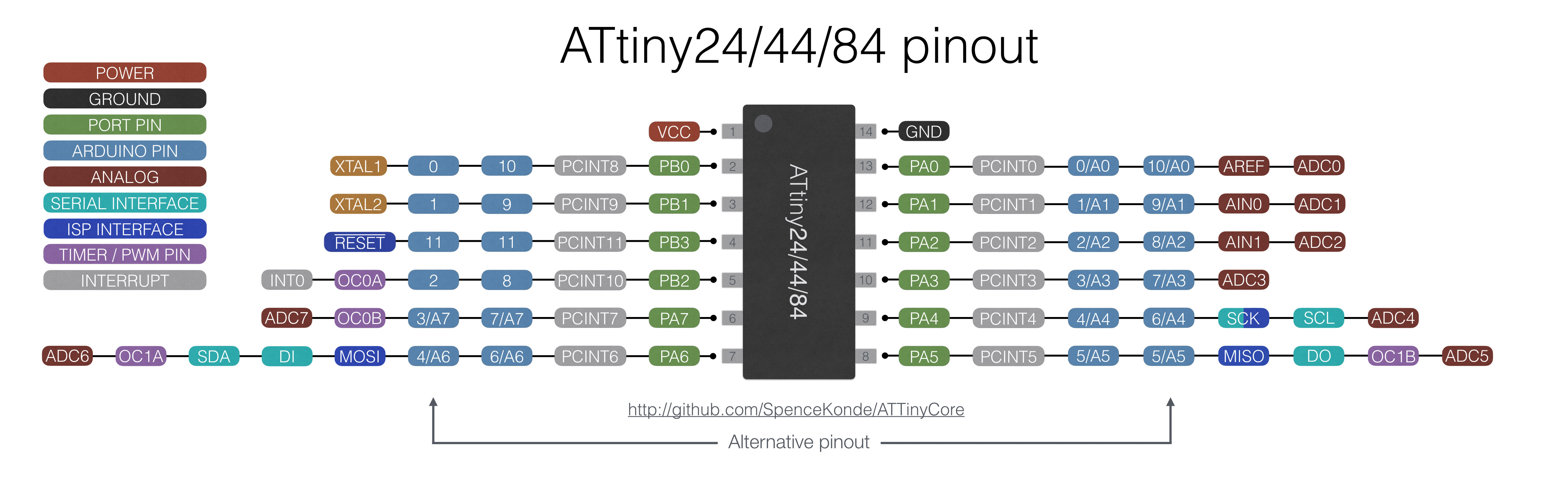
PIN DESCRIPTIONS
VCC
Supply voltage
GND
Ground
Port B (PB3...PB0)
Port B is a 4-bit bi-directional I/O port with internal pull-up resistors (selected for each bit). As inputs, Port B pins that are externally pulled low will source current if the pull-up resistors are activated.so we don't need to add a pull-up resistor externaly for button's and other purpose.
RESET
Reset input. A low level on this pin for longer than the minimum pulse length will generate a reset, even if the clock is not running.a reset will just reset the programm that currently runnig .
Port A (PA7...PA0)
Port A is a 8-bit bi-directional I/O port with internal pull-up resistors (selected for each bit). As inputs, Port A pins that are externally pulled low will source current if the pull-up resistors are activated
Programming ATtiny44 with ARDUINO IDE
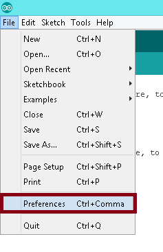
The original arduino software does not support Attint series. So we have to add some udates for that. Go to "file" and click "preference"
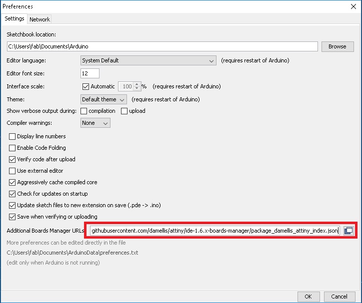
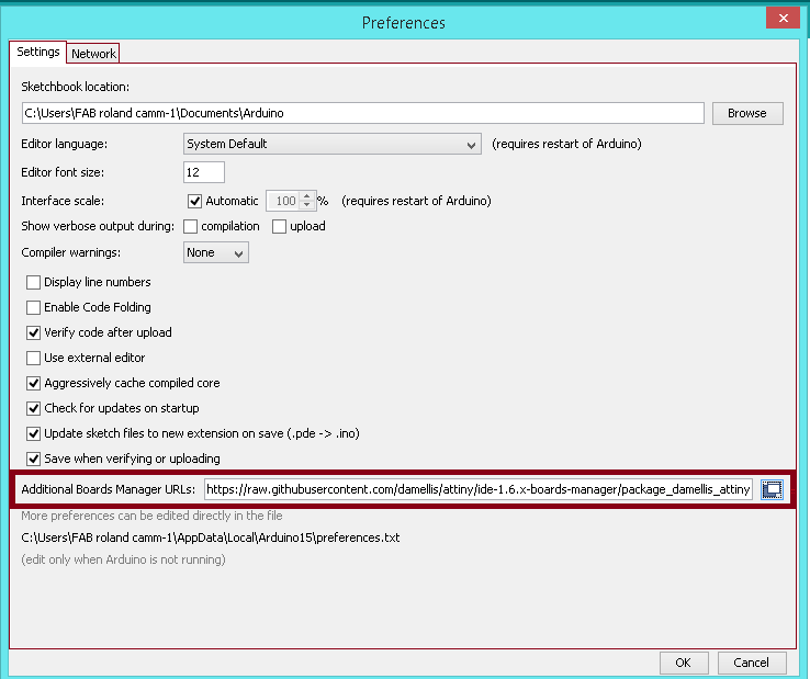
Add following address to the "Additional Board Manager URL"
https://raw.githubusercontent.com/damellis/attiny/ide-1.6.x-boards-manager/package_damellis_attiny_index.json
click "OK"

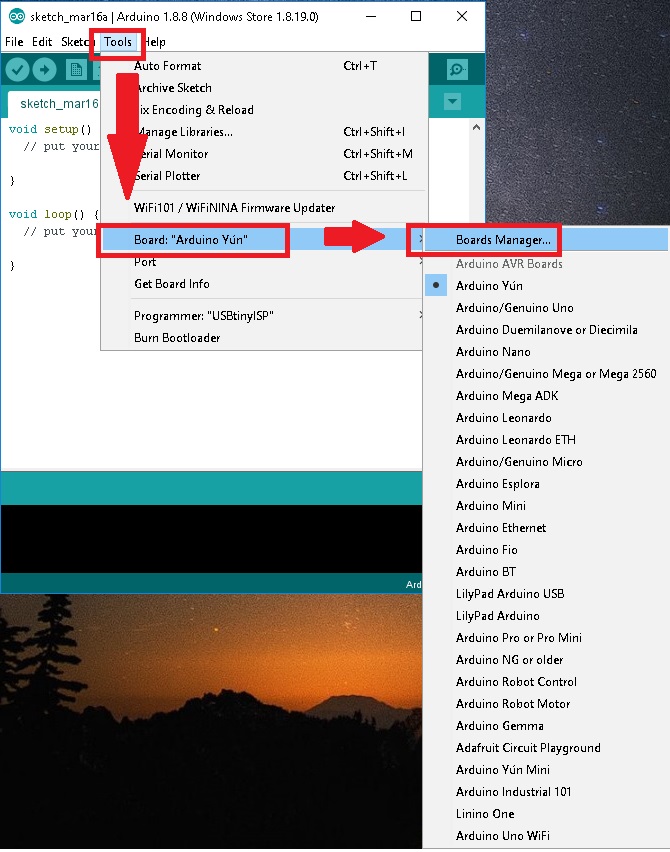
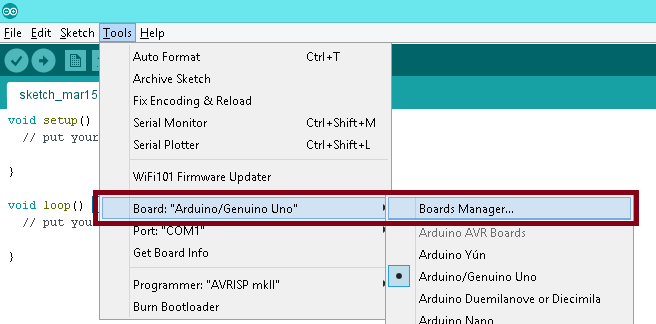
Now to set up the attiny boards, Go to "Tools". Then you can see "Boards". Then click "Board Manager"
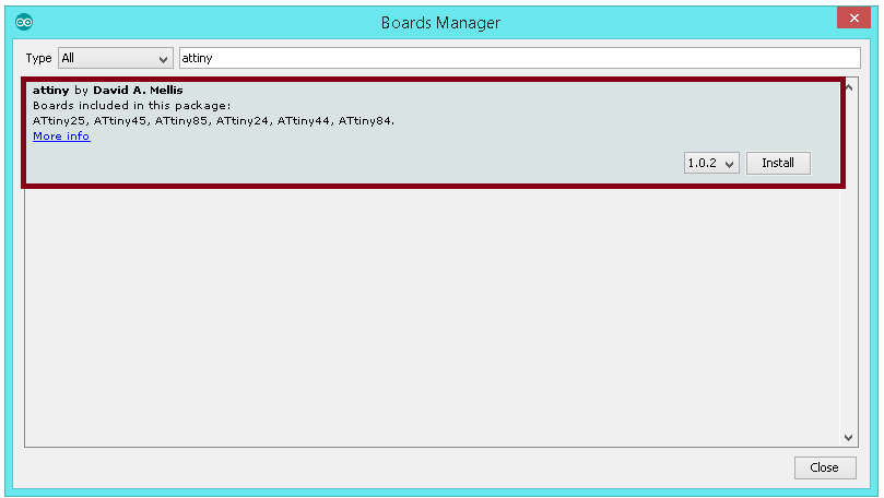
Now search for attiny file in the manager
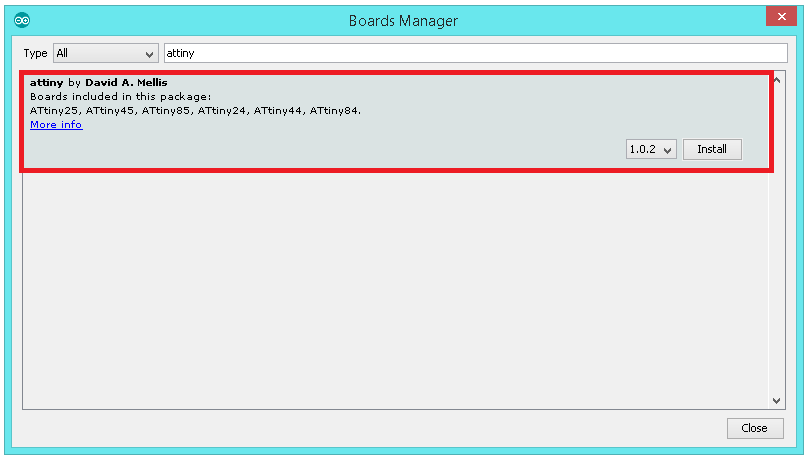
Now you can easily select ATtiny44 under the ATtiny Microcontrollers in board Selection
Programming the Board:
For Programming Echo Hello Board I mainly used Arduino IDE
ARDUINO
Arduino is an open-source electronics platform based on easy-to-use hardware and software.we can tell your board what to do by sending a set of instructions to the microcontroller on the board.
To do so you use the Arduino programming language (based on Wiring), and the Arduino Software (IDE), based on Processing.I felt more easy to use Arduino since i am new to programming.
The Arduino system is based on the avr-gcc compiler and makes use of the standard AVR libc libraries, which are open-source C libraries, specifically written for Atmel hardware.
By default the arduino software doesnt contain Attiny 44 chip librarys. We need to include the deatils manually.
Install and Open Arduino IDE
Open File.Select Preference
Add URL in addtional board manager
After adding the URL
open Board Manager by clicking Tools > Board >Board Manager
Search for ATtiny44 in the Window and select ATtiny44 under the ATtiny Microcontrollers in board Selection.
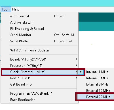
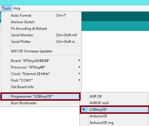
Select appropriate Clock and Programmer.
We are using Fab ISP to programme the Hello-Echo board so Select the Programmer as USBtinyISP.
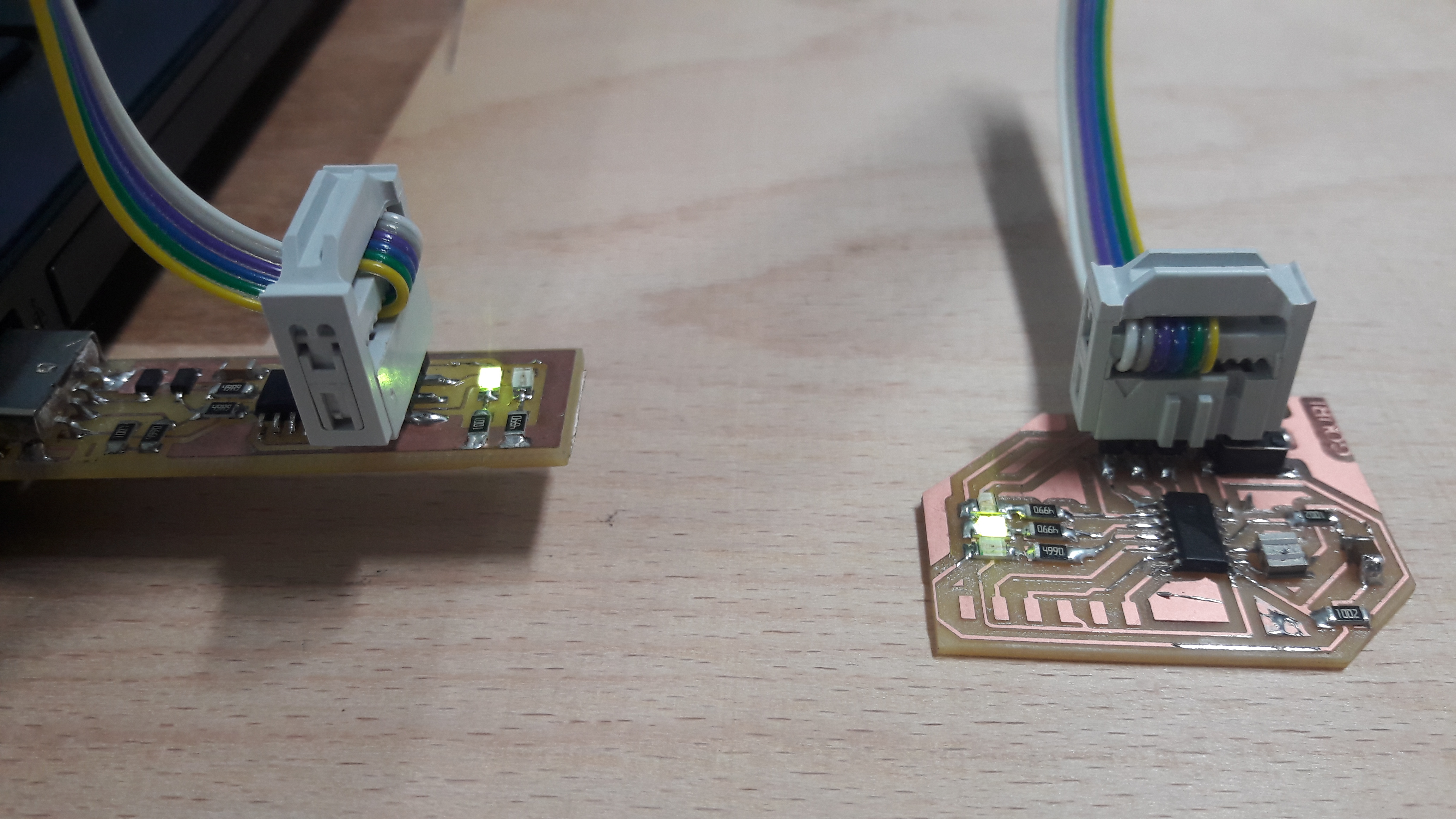
Now we can programm the hello board
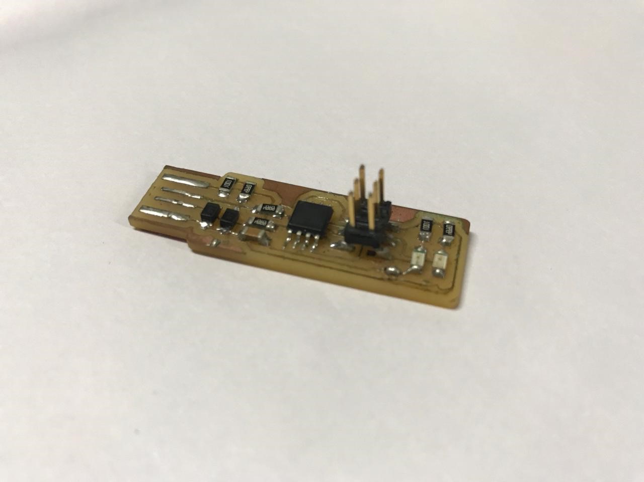
I used my fab isp which was made in electronic production week for programming the helo board.
Arduino Code:
                        void setup() {
                          // put your setup code here, to run once:
                          pinMode {2, OUTPUT};
                          pinMode {3, OUTPUT};
                          pinMode {4, OUTPUT};


                          void loop() {
                            // put your main code here, to run repeatedly:

                            digitalWrite {2 , HIGH};
                            delay {100};
                            digitalWrite {2 , LOW};
                            delay {100};
                            digitalWrite {3 , HIGH};
                            delay {100};
                            digitalWrite {3 , LOW};
                            delay {100};
                            digitalWrite {4 , HIGH};
                            delay {100};
                            digitalWrite {4 , LOW};
                            delay {100};
You can download the Arduino file from here.
    After adding push button
    void setup() {

        pinMode (2, OUTPUT);
        pinMode (3, OUTPUT);    //set 2,3,4 as output (LED)
        pinMode (4, OUTPUT);
        pinMode(7,INPUT);         //set 7 as input (Button)
    }

     void loop(){

        int ButtonData = digitalRead(7);    //store 7 value to ButtonData variable

        if(ButtonData == HIGH)                //check the ButtonData is HIGH (HIGH means button is pressed)
            {
                digitalWrite(2,LOW);
                digitalWrite(3,LOW);
                digitalWrite(4,LOW);              //Turn on the 2,3,4 (LED on)

            }
        else
            {
                digitalWrite(2,HIGH);
                digitalWrite(3,HIGH);
                digitalWrite(4,HIGH);           //Turn off  2,3 ,4 (LED OFF)
            }

     }
You can download the above Arduino file project from here.
Programming ATtiny44 using ATMEL STUDIO
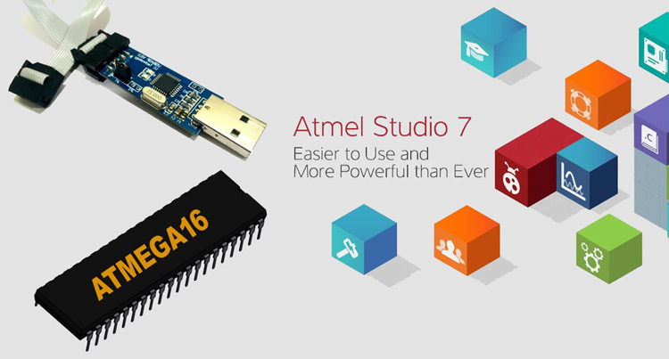
Studio 7 is the integrated development platform (IDP) for developing and debugging all AVR® and SAM microcontroller applications. The Atmel Studio 7 IDP gives you a seamless and easy-to-use environment to write, build and debug your applications written in C/C++ or assembly code. It also connects seamlessly to the debuggers, programmers and development kits that support AVR® and SAM devices.
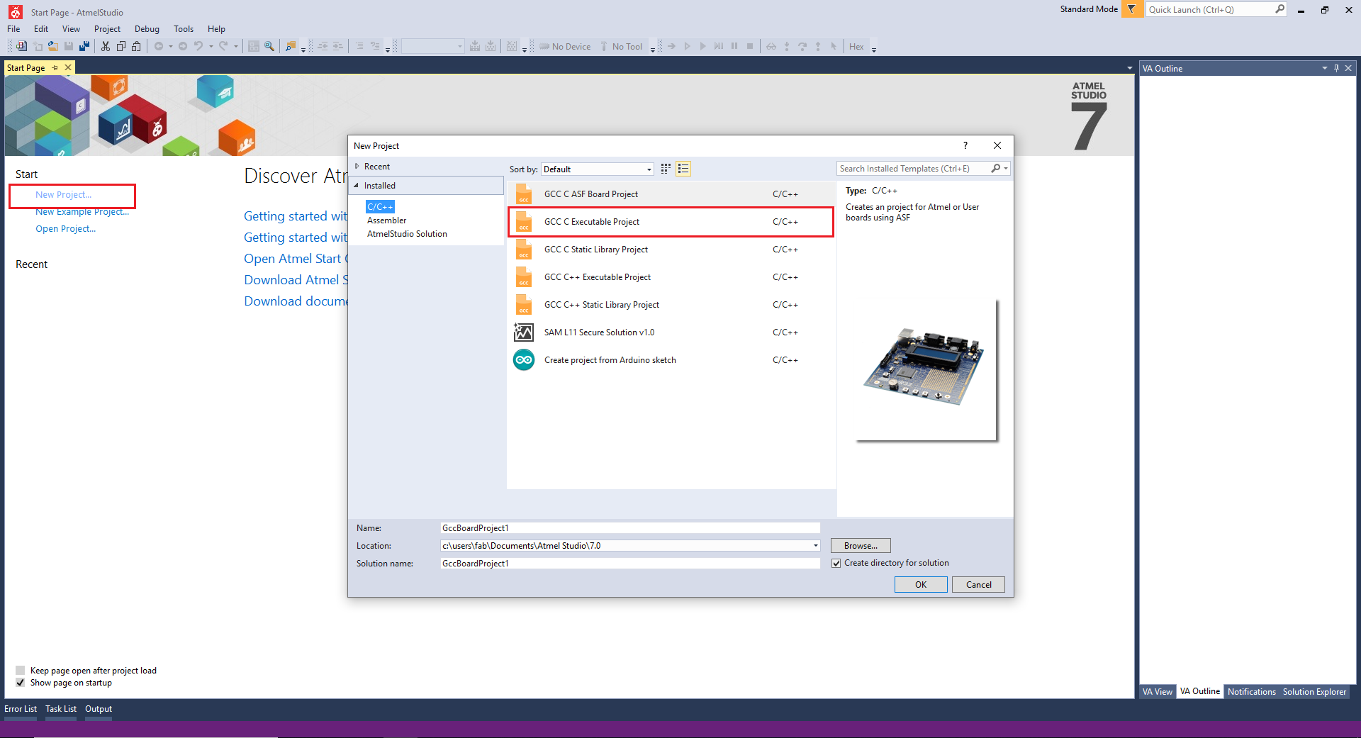
For programming first install and open ATMEL STUDIO. Click "New Project" and srlect"GCC C Exictable project". Click ok to confirm the selection
For programming first install and open ATMEL STUDIO. Click "New Project" and select"GCC C Exictable project". Click ok to confirm the selection
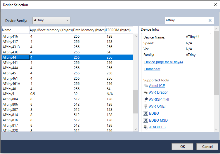
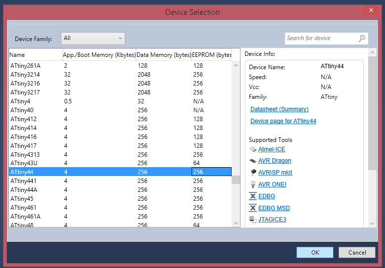
Now you can see the following window. Select device famiy as Attiny and select Attint 44. Click ok to confirm the operation.
Now you will get a window.
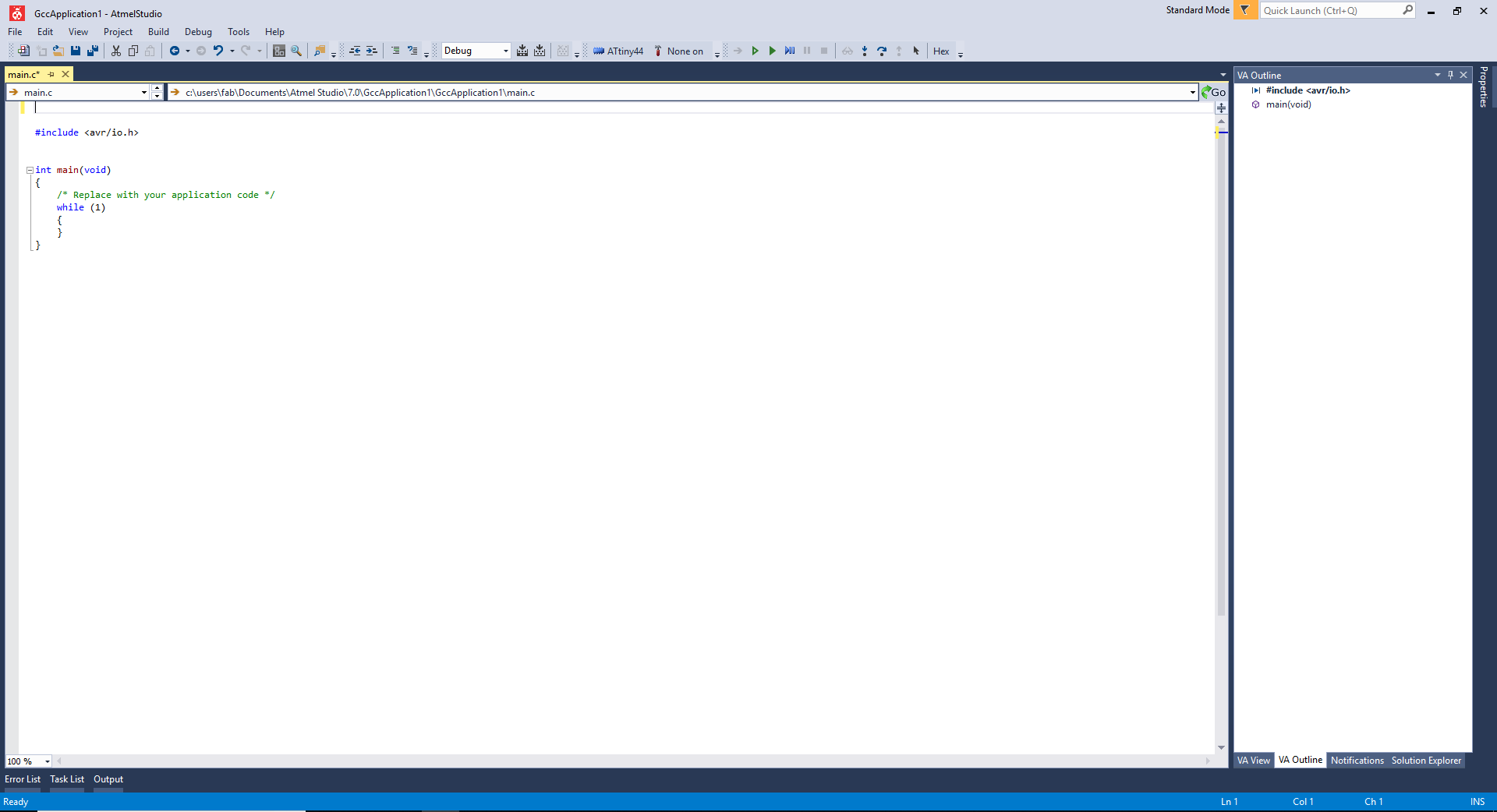
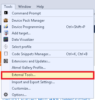
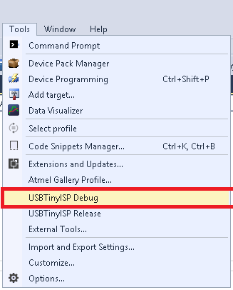
Now we need to setup some parameters for usbtiny debugging. For that Go to "Tools" and Select "External Tools."
Add following details to the box:
Debug Version
Title:- USBTiny ISP Debug
Command :- avrdude.exe
Arguments :- -c usbtiny -p attiny44 -U flash:w:$(ProjectDir)Debug\$(TargetName).hex:i
click apply and ok to save the tool.
Release Version
Title:- USBTiny ISP Release.
Command :- avrdude.exe
Arguments :- -c usbtiny -p attiny44 -U flash:w:$(ProjectDir)Release\$(TargetName).hex:i
click apply and ok to save the tool.
Start a Project by clicking File >> New >> Project
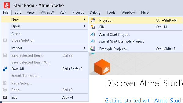
Now select C/C++ as language and Template as GCC C Executable Project give a name and click OK.
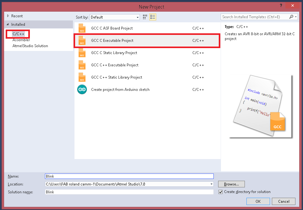
Then Select the Target Microcontroller , in here we have ATtiny44.
                    #define F_CPU 20000000UL      //Clock 20-Mhz
                    #include <avr/io.h>


                    int main(void)
                    {

                      DDRA |= (1 << 2);   // Set PA2 as OUTPUT for Red led
                      DDRA |= (1 << 3);  // Set PA3 as OUTPUT for Yellow led
                      DDRA |= (1 << 4); // set PA4 as OUPUT for Blue led


                      DDRA &= ~ (1 << 7);   //Set PA2 as INPUT for Button


                      while (1)
                      {
                        if (PINA & (1 << 2)) //check whether the button pressed or not
                        {
                          PORTA = PORTA | (1 << 2); // Turn on Red led
                          PORTA = PORTA | (1 << 3); // Turn on Yellow led
                          PORTA = PORTA | (1 << 4); // Turn on Blue led


                        }
                        else
                        {
                          PORTA &= ~(1 << 2);   // Turn on RED led
                          PORTA &= ~(1 << 2);   // Turn on Yellow led
                          PORTA &= ~(1 << 2);   // Turn on Blue led
                        }

                      }
                    }
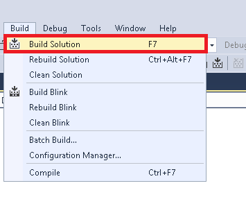
For Uploading code first we need to build/compile it by using Build > Build Soution
After the compailation we need to flash the code in to our board
The output is same as the Arduino.by clicking the button to flash the leds.